
انجمن مدیران و راهبران شبکه
Network Managers and Administrators
انجمن مدیران و راهبران شبکه
Network Managers and Administratorsفایل تکمیل شده یک سناریوی ساده از شبکه ای مشتمل بر چند سگمنت- دوره آموزشی مرکز آپا تابستان 1392- دانشگاه فردوسی مشهد
Work shop # 1
A Simple Converged Multi VLANs Campus Network Scenario :
VTP Domain, VLAN configuration, Trunking, Inter-VLAN routing
مشخصات فنی سناریو :
APA-Core#sho vtp status
VTP Version : 2
Configuration Revision : 22
Maximum VLANs supported locally : 1005
Number of existing VLANs : 8
VTP Operating Mode : Server
VTP Domain Name : APA
VTP Pruning Mode : Disabled
VTP V2 Mode : Enabled
VTP Traps Generation : Disabled
MD5 digest : 0x50 0x54 0x07 0x67 0xBE 0xE6 0x92 0x02
Configuration last modified by 0.0.0.0 at 3-1-93 00:00:00
Local updater ID is 192.168.1.1 on interface Vl1 (lowest numbered VLAN interface found)
APA-Core#
APA-Core#sho vtp password
VTP Password: cisco
APA-Core#
جهت دانلود فایل تکمیل شده در نرم افزار شبیه ساز Cisco Packet Tracer v6.0 اینجا کلیک نمایید.
نحوه تست دیود زنر
Meter check of a diode
Being able to determine the polarity (cathode versus anode) and basic functionality of a diode is a very important skill for the electronics hobbyist or technician to have. Since we know that a diode is essentially nothing more than a one-way valve for electricity, it makes sense we should be able to verify its one-way nature using a DC (battery-powered) ohmmeter as in Figure below. Connected one way across the diode, the meter should show a very low resistance at (a). Connected the other way across the diode, it should show a very high resistance at (b) (“OL” on some digital meter models).

Determination of diode polarity: (a) Low resistance indicates forward bias, black lead is cathode and red lead anode (for most meters) (b) Reversing leads shows high resistance indicating reverse bias.
Of course, to determine which end of the diode is the cathode and which is the anode, you must know with certainty which test lead of the meter is positive (+) and which is negative (-) when set to the “resistance” or “Ω” function. With most digital multimeters I've seen, the red lead becomes positive and the black lead negative when set to measure resistance, in accordance with standard electronics color-code convention. However, this is not guaranteed for all meters. Many analog multimeters, for example, actually make their black leads positive (+) and their red leads negative (-) when switched to the “resistance” function, because it is easier to manufacture it that way!
One problem with using an ohmmeter to check a diode is that the readings obtained only have qualitative value, not quantitative. In other words, an ohmmeter only tells you which way the diode conducts; the low-value resistance indication obtained while conducting is useless. If an ohmmeter shows a value of “1.73 ohms” while forward-biasing a diode, that figure of 1.73 Ω doesn't represent any real-world quantity useful to us as technicians or circuit designers. It neither represents the forward voltage drop nor any “bulk” resistance in the semiconductor material of the diode itself, but rather is a figure dependent upon both quantities and will vary substantially with the particular ohmmeter used to take the reading.
For this reason, some digital multimeter manufacturers equip their meters with a special “diode check” function which displays the actual forward voltage drop of the diode in volts, rather than a “resistance” figure in ohms. These meters work by forcing a small current through the diode and measuring the voltage dropped between the two test leads. (Figure below)
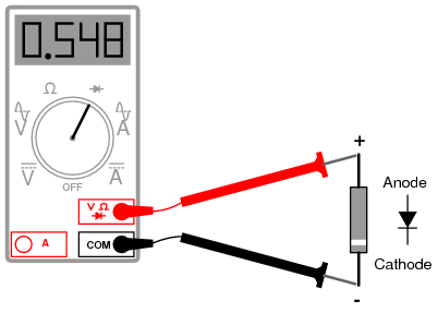
Meter with a “Diode check” function displays the forward voltage drop of 0.548 volts instead of a low resistance.
The forward voltage reading obtained with such a meter will typically be less than the “normal” drop of 0.7 volts for silicon and 0.3 volts for germanium, because the current provided by the meter is of trivial proportions. If a multimeter with diode-check function isn't available, or you would like to measure a diode's forward voltage drop at some non-trivial current, the circuit of Figure below may be constructed using a battery, resistor, and voltmeter
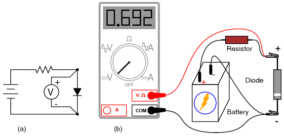
Measuring forward voltage of a diode without“diode check” meter function: (a) Schematic diagram. (b) Pictorial diagram.
Connecting the diode backwards to this testing circuit will simply result in the voltmeter indicating the full voltage of the battery.
If this circuit were designed to provide a constant or nearly constant current through the diode despite changes in forward voltage drop, it could be used as the basis of a temperature-measurement instrument, the voltage measured across the diode being inversely proportional to diode junction temperature. Of course, diode current should be kept to a minimum to avoid self-heating (the diode dissipating substantial amounts of heat energy), which would interfere with temperature measurement.
Beware that some digital multimeters equipped with a “diode check” function may output a very low test voltage (less than 0.3 volts) when set to the regular “resistance” (Ω) function: too low to fully collapse the depletion region of a PN junction. The philosophy here is that the “diode check” function is to be used for testing semiconductor devices, and the “resistance” function for anything else. By using a very low test voltage to measure resistance, it is easier for a technician to measure the resistance of non-semiconductor components connected to semiconductor components, since the semiconductor component junctions will not become forward-biased with such low voltages.
Consider the example of a resistor and diode connected in parallel, soldered in place on a printed circuit board (PCB). Normally, one would have to unsolder the resistor from the circuit (disconnect it from all other components) before measuring its resistance, otherwise any parallel-connected components would affect the reading obtained. When using a multimeter which outputs a very low test voltage to the probes in the “resistance” function mode, the diode's PN junction will not have enough voltage impressed across it to become forward-biased, and will only pass negligible current. Consequently, the meter “sees” the diode as an open (no continuity), and only registers the resistor's resistance. (Figure below)

Ohmmeter equipped with a low test voltage (<0.7 V) does not see diodes allowing it to measure parallel resistors.
If such an ohmmeter were used to test a diode, it would indicate a very high resistance (many mega-ohms) even if connected to the diode in the “correct” (forward-biased) direction. (Figure below)

Ohmmeter equipped with a low test voltage, too low to forward bias diodes, does not see diodes.
Reverse voltage strength of a diode is not as easily tested, because exceeding a normal diode's PIV usually results in destruction of the diode. Special types of diodes, though, which are designed to “break down” in reverse-bias mode without damage (called zener diodes), which are tested with the same voltage source / resistor / voltmeter circuit, provided that the voltage source is of high enough value to force the diode into its breakdown region. More on this subject in a later section of this chapter.
- REVIEW:
- An ohmmeter may be used to qualitatively check diode function. There should be low resistance measured one way and very high resistance measured the other way. When using an ohmmeter for this purpose, be sure you know which test lead is positive and which is negative! The actual polarity may not follow the colors of the leads as you might expect, depending on the particular design of meter.
- Some multimeters provide a “diode check” function that displays the actual forward voltage of the diode when its conducting current. Such meters typically indicate a slightly lower forward voltage than what is “nominal” for a diode, due to the very small amount of current used during the check.
نحوه تهیه گزارش از سابقه اتصال کاربران VPN بر روی سرور Forfront TMG
سلام،
ممکنه برای شبکه تحت کنترل شما هم شرایطی از لحاظ امنیتی پیش بیاد که لازم باشه سابقه اتصالات کاربران راه دور که از طریق VPN به سرور ISA یا Forefront TMG متصل می شوند تحت قالب یک گزارش تهیه و بررسی نمایید.برای این منظور می توانید از روش زیر به منظور تهیه گزارش مورد نظر استفده کنید:
توجه : من مراحل تهیه گزارش رو در MS ISA 2006 توضیح دادم که شما می تونید مشابه همین مراحل رو از منوی Logs and Reports نرم افزار Forefront TMG دنبال کنید.
1- ابتدا پنجره ISA Management Console رو باز کنید.
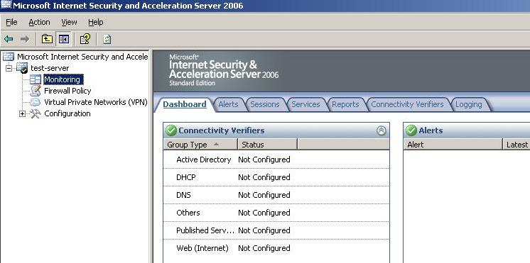
2- در نود Monitoring بر روی زبانه Logging کلیک کنید :
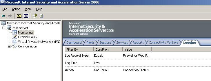
3- در این قسمت گزارشی رو با در نظر گرفتن 2 فیلتر زیر ایجاد می کنیم:
- Logging Last 30 Days
- Action Equals Initiated VPN Connection
4- بر روی عبارت Edit filter کلیک می کنیم تا بتونیم فیلترهای مورد نظرمون رو اضافه کنیم.
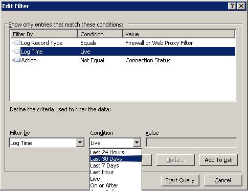
5- در منوی باز شده بر روی عبارت Log Time کلیک کنید و از منوی باز شو عبارت Last 30 Days رو انتخاب و بعد دکمه Update رو انتخاب کنید.
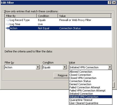
6- حالا بر روی منوی Action کلیک کنید، از منوی باز شوی Condition عبارت Equal رو انتخاب و از منوی بازشوی Value گزینه Initiated VPN Connection رو انتخاب و در آخر مجددا بر روی دکمه Update کلیک کنید.
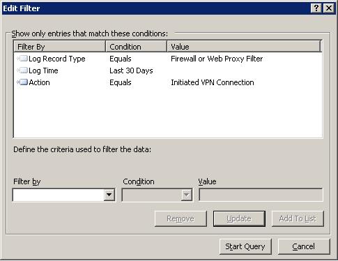
7- در نهایت فیلتر ایجاد شده باید مثل تصویر زیر باشد :
8- حالا می تونید با کلیک بر روی دکمه Start Query ، گزارش مورد نظرتون رو تهیه کنید. در این گزارش به عنوان مثال سابقه اتصالات کاربران در 30 روز گذشته نمایش داده خواهد شد.

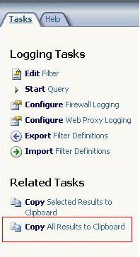
9- حالا اگه می خواین گزارش تهیه شده رو به فایل اکسلی تبدیل کنید کافیه تا از منوی سمت راست زیر عبارت Task، گزینه Copy All Result to Clipboard رو انتخاب کنید.
10 - و در نهایت با باز کردن یک فایل جدید در MS Excel ، اطلاعات کپی شده را Paste کنید.
خوب تا اینجا تونستید گزارش این موضوع که "در 30 روز گذشته چه کسی به شبکه متصل شده؟ " رو تهیه کنید ولی اگر بخواهید گزارشی در پاسخ به این سوال که "کاربران متصل شده، به چه منابعی در شبکه داخلی دسترسی پیدا کردند؟" تهیه کنید، باید فیلتر ایجاد شده رو به شکل زیر تغییر بدید :
11- خوب مطمئنا اگر با سیستم های فایروالی نظیر ISA,Forefront TMG یا Cisco ASA آشنایی داشته باشید قطعا می دونید که برای اینکه کاربران گروه VPN بتونن بعد از اتصال به شبکه، به منابع مجازی بر روی شبکه که شما تعیین می کنید دسترسی داشته باشند، نیاز به ایجاد یک Access Rule به شکل زیر خواهد بود :

توجه کنید که در این مثال، نام تعیین شده برای این Firewall Policy عبارت " VPN Inbound Access" می باشد.
12 - خوب حالا فیلتر تهیه شده در مرحله قبل رو بصورت زیر ویرایش کنید :

13- حالا با کلیک بر روی دکمه Start Query میتونید گزارش منابع دسترسی شده توسط کاربران VPN رو تهیه کنید.
موفق و سربلند باشید. 
رفع مشکل ناهماهنگی لایسنس با ورژن آنتی ویروس Kaspersky

kaspersky license incompatibility
برای دانلود دستورالعمل و فایل های مورد نیاز اینجا کلیک نمایید.
Samsung
Info+menu+mute+power
هیچی دیگه ، همین !!! 
بازم نوشتم که فراموش نکنم. هرکی فهمید این چیه نازه شستش.
با تشکر از دوست عزیزم: میثم.